INJECTION MOULDING
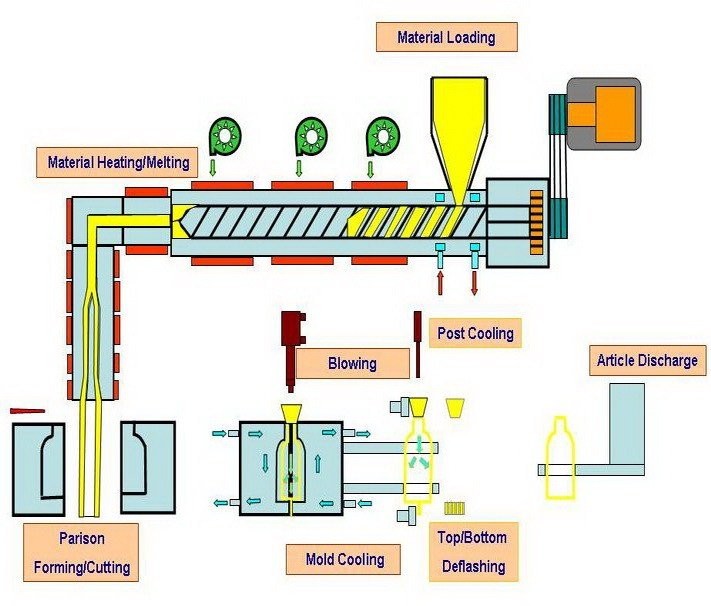
Injection moulding is a manufacturing process for producing parts by injecting material into a mould. Injection moulding can be performed with a host of materials mainly including metals, (for which the process is called die-casting), glasses, elastomers, confections, and most commonly thermoplastic and thermosetting polymers.
Material for the part is fed into a heated barrel, mixed, and forced into a mould cavity, where it cools and hardens to the configuration of the cavity. After a product is designed, usually by an industrial designer or an engineer, moulds are made by a mould an injection moulding machine maker (or toolmaker) from metal, usually either steel or aluminium, and precision-machined to form the features of the desired part.
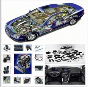
Injection moulding is widely used for manufacturing a variety of parts, from the smallest components to entire body panels of cars. Advances in 3D printing technology, using photo polymers which do not melt during the injection moulding of some lower temperature thermoplastics, can be used for some simple injection moulds.
PROCESS:
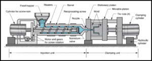
Injection moulding uses a ram or screw-type plunger to force molten plastic material into a mould cavity; this solidifies into a shape that has conformed to the contour of the mould. It is most commonly used to process both thermoplastic and thermosetting polymers, with the volume used of the former being considerably higher. Thermoplastics are prevalent due to characteristics which make them highly suitable for injection moulding, such as the ease with which they may be recycled, their versatility allowing them to be used in a wide variety of applications, and their ability to soften and flow upon heating. Thermoplastics also have an element of safety over thermosets; if a thermosetting polymer is not ejected from the injection barrel in a timely manner, chemical cross linking may occur causing the screw and check valves to seize and potentially damaging the injection moulding machine.
Injection moulding consists of the high pressure injection of the raw material into a mould which shapes the polymer into the desired shape. Moulds can be of a single cavity or multiple cavities. In multiple cavity moulds, each cavity can be identical and form the same parts or can be unique and form multiple different geometries during a single cycle. Moulds are generally made from tool steels, but stainless steels and aluminium moulds are suitable for certain applications. Aluminium moulds are typically ill-suited for high volume production or parts with narrow dimensional tolerances, as they have inferior mechanical properties and are more prone to wear, damage, and deformation during the injection and clamping cycles; however, aluminium moulds are cost-effective in low-volume applications, as mould fabrication costs and time are considerably reduced.
Many steel moulds are designed to process well over a million parts during their lifetime and can cost hundreds of thousands of dollars to fabricate.
When thermoplastics are moulded, typically palletised raw material is fed through a hopper into a heated barrel with a reciprocating screw. Upon entrance to the barrel, the temperature increases and the Van der Waals forces that resist relative flow of individual chains are weakened as a result of increased space between molecules at higher thermal energy states. This process reduces its viscosity, which enables the polymer to flow with the driving force of the injection unit. The screw delivers the raw material forward, mixes and homogenizes the thermal and viscous distributions of the polymer, and reduces the required heating time by mechanically shearing the material and adding a significant amount of frictional heating to the polymer. The material feeds forward through a check valve and collects at the front of the screw into a volume known as a shot.
A shot is the volume of material that is used to fill the mould cavity, compensate for shrinkage, and provide a cushion (approximately 10% of the total shot volume, which remains in the barrel and prevents the screw from bottoming out) to transfer pressure from the screw to the mould cavity. When enough material has gathered, the material is forced at high pressure and velocity into the part forming cavity. To prevent spikes in pressure, the process normally uses a transfer position corresponding to a 95–98% full cavity where the screw shifts from a constant velocity to a constant pressure control. Often injection times are well under 1 second. Once the screw reaches the transfer position the packing pressure is applied, which completes mould filling and compensates for thermal shrinkage, which is quite high for thermoplastics relative to many other materials. The packing pressure is applied until the gate (cavity entrance) solidifies. Due to its small size, the gate is normally the first place to solidify through its entire thickness.
Once the gate solidifies, no more material can enter the cavity; accordingly, the screw reciprocates and acquires material for the next cycle while the material within the mould cools so that it can be ejected and be dimensionally stable. This cooling duration is dramatically reduced by the use of cooling lines circulating water or oil from an external temperature controller. Once the required temperature has been achieved, the mould opens and an array of pins, sleeves, strippers, etc. are driven forward to de-mould the article. Then, the mould closes and the process is repeated.
For a two shot mould, two separate materials are incorporated into one part. This type of injection moulding is used to add a soft touch to knobs, to give a product multiple colours, to produce a part with multiple performance characteristics.
For thermosets, typically two different chemical components are injected into the barrel. These components immediately begin irreversible chemical reactions which eventually cross links the material into a single connected network of molecules. As the chemical reaction occurs, the two fluid components permanently transform into a visco-elastic solid.
Solidification in the injection barrel and screw can be problematic and have financial repercussions; therefore, minimising the thermoset curing within the barrel is vital. This typically means that the residence time and temperature of the chemical precursors are minimised in the injection unit. The residence time can be reduced by minimising the barrel’s volume capacity and by maximising the cycle times.
These factors have led to the use of a thermally isolated, cold injection unit that injects the reacting chemicals into a thermally isolated hot mould, which increases the rate of chemical reactions and results in shorter time required to achieve a solidified thermoset component. After the part has solidified valves close to isolate the injection system and chemical precursors, and the mould opens to eject the moulded parts. Then, the mould closes and the process repeats.
Pre-moulded or machined components can be inserted into the cavity while the mould is open, allowing the material injected in the next cycle to form and solidify around them. This process is known as Insert moulding and allows single parts to contain multiple materials. This process is often used to create plastic parts with protruding metal screws, allowing them to be fastened and unfastened repeatedly. This technique can also be used for In-mould labelling and film lids may also be attached to moulded plastic containers.
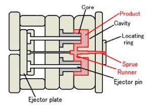
A parting line, sprue, gate marks, and ejector pin marks are usually present on the final part. None of these features are typically desired, but are unavoidable due to the nature of the process. Gate marks occur at the gate which joins the melt-delivery channels (sprue and runner) to the part forming cavity. Parting line and ejector pin marks result from minute mis-alignments, wear, gaseous vents, clearances for adjacent parts in relative motion, and/or dimensional differences of the mating surfaces contacting the injected polymer.
Dimensional differences can be attributed to non-uniform, pressure-induced deformation during injection, machining tolerances, and non-uniform thermal expansion and contraction of mould components, which experience rapid cycling during the injection, packing, cooling, and ejection phases of the process. Mould components are often designed with materials of various coefficients of thermal expansion. These factors cannot be simultaneously accounted for without astronomical increases in the cost of design, fabrication, processing, and quality monitoring. The skilful mould and part designer will position these aesthetic detriments in hidden areas if feasible.
EQUIPMENT CONSISTED BY AN INJECTION MOULDING:
Injection moulding machines consist of a material hopper, an injection ram or screw-type plunger, and a heating unit. Also known as platens, they hold the moulds in which the components are shaped. Presses are rated by tonnage, which expresses the amount of clamping force that the machine can exert.
This force Equipment keeps the mould closed during the injection process. Tonnage can vary from less than 5 tons to over 9,000 tons, with the higher figures used in comparatively few manufacturing operations. The total clamp force needed is determined by the projected area of the part being moulded. This projected area is multiplied by a clamp force of from 1.8 to 7.2 tons for each square centimeter of the projected areas. As a rule of thumb, 4 or 5 tons/in2 can be used for most products.
If the plastic material is very stiff, it will require more injection pressure to fill the mould, and thus more clamp tonnage to hold the mould closed. The required force can also be determined by the material used and the size of the part. Larger parts require higher clamping force.
Mould or die are the common terms used to describe the tool used to produce plastic parts in moulding.
Since moulds have been expensive to manufacture, they were usually only used in mass production where thousands of parts were being produced. Typical moulds are constructed from hardened steel, pre-hardened steel, aluminium, and/or beryllium-copper alloy. The choice of material to build a mould from is primarily one of economics; in general, steel moulds cost more to construct, but their longer lifespan will offset the higher initial cost over a higher number of parts made before wearing out.
Pre-hardened steel moulds are less wear-resistant and are used for lower volume requirements or larger components; their typical steel hardness is 38–45 on the Rockwell-C scale. Hardened steel moulds are heat treated after machining; these are by far superior in terms of wear resistance and lifespan. Typical hardness ranges between 50 and 60 Rockwell-C (HRC). Aluminium moulds can cost substantially less, and when designed and machined with modern computerised equipment can be economical for moulding tens or mould even hundreds of thousands of parts.
Beryllium copper is used in areas of the mould that require fast heat removal or areas that see the most shear heat generated. The moulds can be manufactured either by CNC machin or by using electrical discharge machining processes.
Mould storage
Manufacturers go to great lengths to protect custom moulds due to their high average costs. The perfect temperature and humidity level is maintained to ensure the longest possible lifespan for each custom mould. Custom moulds, such as those used for rubber injection moulding, are stored in temperature and humidity controlled environments to prevent warping.
Injection Process:
With injection moulding, granular plastic is fed by a forced ram from a hopper into a heated barrel. As the granules are slowly moved forward by a screw-type plunger, the plastic is forced into a heated chamber, where it is melted. As the plunger advances, the melted plastic is forced through a nozzle that rests against the mould, allowing it to enter the mould cavity through a gate and runner system. The mould remains cold so the plastic solidifies almost as soon as the mould is filled.
Injection Moulding Cycle:
The sequence of events during the injection mould of a plastic part is called the injection moulding cycle. The cycle begins when the mould closes, followed by the injection of the polymer into the mould cavity. Once the cavity is filled, a holding pressure is maintained to compensate for material shrinkage. In the next step, the screw turns, feeding the next shot to the front screw. This causes the screw to retract as the next shot is prepared. Once the part is sufficiently cool, the mould opens and the part is ejected.
Moulding Defects:
Injection moulding is a complex technology with possible production problems. They can be caused either by defects in the moulds, or more often by the moulding process itself.
Mould Defects |
Descriptions |
Causes |
| Blistering | Raised or layered zone on surface of the part | Tool or material is too hot, often caused by a lack of cooling around the tool or a faulty heater |
| Air burn/gas bur/gas marks/Blow marks | Black or brown burnt areas on the part located at furthest points from gate or where air is trapped | Tool lacks venting, injection speed is too high |
| Color Streaks | Localized change in color | Master batch isn’t mixing properly, or the material has run out and it’s starting to come through as natural only. Previous coloured
material “dragging” in nozzle or check valve |
| Delamination | Thin mica like layers formed in walls | Contamination of the material e.g. PP mixed with ABS, very dangerous if the part is being used for a safety critical application as the material has very little strength when delaminated as the materials cannot bond |
| Flash | Excess material in thin layer exceeding normal part geometry | Mould is over packed or parting line on the tool is damaged, too much injection speed/material injected, clamping force too low. Can also be caused by dirt and contaminants around tooling surfaces |
| Flow Marks | Directionally “off tone” wavy lines or patterns | Injection speeds too slow (the plastic has cooled down too much during injection, injection speeds should be set as fast as is appropriate for the process and material used) |
| Polymer Degradation | Breakdown from hydrolysis oxidation etc. | Excess water in granules, excessive temperatures in barrel, excessive screw speeds causing high shear heat, material being allowed to sit in the barrel for too long, too much regrind being used. |
| Sink Marks | Localized depression in thicker zones | Holding time/pressure too low, cooling time too short, with sprueless hot runners this can also be caused by the gate temperature being set too high. Excessive material or walls too thick |
| Short Shot | Partial part | Lack of material, injection speed or pressure too low, mould too cold, lack of gas vents |
| Voids | Empty space with in a part | Lack of holding pressure (holding pressure is used to pack out the part during the holding time). Filling too fast, not allowing the edges of the part to set up. Also mould may be out of registration (when the two halves don’t centre properly and part walls are not the same thickness). The provided information is the common understanding, Correction: The Lack of pack (not holding) pressure (pack pressure is used to pack out even though is the part during the holding time). Filling too fast does not cause this condition, as a void is a
sink that did not have a place to happen. In other words, as the part shrinks the resin separated from itself as there was not sufficient resin in the cavity. The void could happen at any area or the part is not limited by the thickness but by the resin flow and thermal conductivity, but it is more likely to happen at thicker areas like ribs or bosses. Additional root causes for voids are un-melt on the melt pool |
| Weld Line | Discoloured line where two flow fronts meet | Mould or material temperatures set too low (the material is cold when they meet, so they don’t bond). Time for transition between
injection and transfer (to packing and holding) is too early. |
| Wrapage or twisting | Distorted part | Cooling is too short, material is too hot, lack of cooling around the tool, incorrect water temperatures (the parts bow inwards towards the hot side of the tool) Uneven shrinking between areas of the part |
| Cracks | Improper fusion of two fluid flow | Threadline gap in between part due to improper gate location in complex design parts including excess of holes (multipoint gates to be provided), process optimization, proper air venting |
Materials mostly used:
Material Specific Gravity Melting point (°C)
Epoxy 1.12 to 1.24 120
Phenolic 1.34 to 1.95 120
Nylon 1.01 to 1.15 194 to 265
Polyethylene 0.91 to 0.965 110 to 117
Polystyrene 1.04 to 1.07 170
Uses or Applications:
 Injection moulding is used to create many things such as wire spools, packaging, bottle caps, automotive parts and components, game boys, pocket combs, some musical instruments (and parts of them), one-piece chairs and small tables, storage containers, mechanical parts (including gears), and most other plastic products available today. Injection moulding is the most common modern method of manufacturing plastic parts; it is ideal for producing high volumes of the same object.


