MICRO PROCESSOR CONTROL: OPEN LOOP AND CLOSE LOOP
Why Micro processor required?
To ensure consistency of quality of injection moulded parts one has to look at the controls like pressure, speed, stroke & temperature. This is the reputability of the product quality with closed tolerance on dimension and weight throughout long production gone. The injection moulding process control is quite complex because of the interplay among the process parameters, i.e moulding temperature, viscosity, pressure, speed, resident time etc.
The failure of the parameter set can “drift” on account of
• Any variation in the material
• Density
• MFI
• Molecular weight, etc.
• Inaccuracies in repetition of set values of hydraulic valves like
• Pressure relief valve and
• For control valve
This drift upsets the process balance and repeatability. In term, this can result in inconsistent quality of moulded part. Therefore, the parameters are required to be controlled to get quality moulded part.
So, the desired control is wanted to be achieved, but the micro processor along is not enough and it requires the matching support for the hydraulic control gears. The micro processor is brain and the hydraulic power is drawn for well designed injection moulding machines. Micro processor control offers improved accuracy, efficiency and versatility because of its high speed reasons, programmeability and computational ability.
Micro Processor Control:
The advanced semi conduct of technology enables to get large scale integrated logic circuit in tiny silicon water enclosed in a small plastic case. This micro processor has replaced conventional hardwired contractor logic circuits.
• The micro processor programmable logic control include
• Micro processor to perform login operation
• Memory to hold programme and data
• Input output device, that is, alfa numeric keypad etc.
• Peripheral device, that is limit switches, digital switches, proximity
• Switches, thumb wheel switches
One can actually change the programmed of micro processor to change the sequence or programs at a letter data quite easily in this machine. Normally core cooling ejector programs requires alteration to suit this design of the mould.
In addition, micro processor in injection moulding machines has to perform very complex and power full operations involving logic, probability, competition, decision making. In this operation all the relevant data are represented and processed in a digital form precisely at high speeds.
The micro processor is capable accepting, processing and giving an output in both analogue and digital signals. Analogue signal is comparable to time shown by two hands of a mechanical watch. Digital signal can be compared to the time shown on digital quartz watch.
Analogue input and output include temperature, pressure, speed distance etc.

Faults and Remedies:
Air Traps (Voice and bobbles):
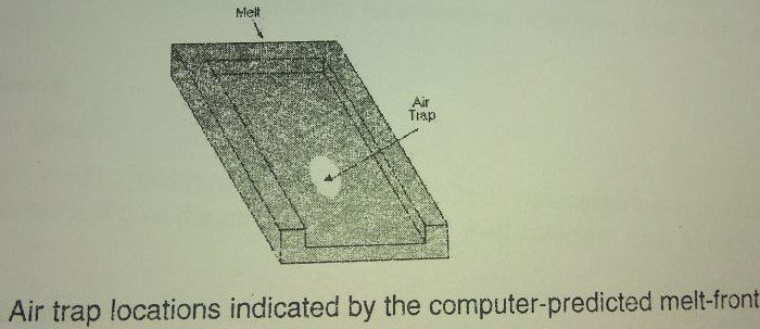
An air trap is air that is caught inside the mould cavity. It becomes trapped by covering polymeric melt fronts or because it failed to escape from the mould vents, or mould inserts, which also as vents. Air trap locations are usually in areas that fill last. Lack of vents or undersized vents in these last two fill areas are a common causes of a air trap and the resulting defects. Another common causes is race tracking (the tendency of polymer melt to flow preferentially in thicker sections), caused by a large thickness ratio.
Problems Caused by air traps:
Entrapped air will result in voids and bobbles, inside the moulded part, a sort shot (incomplete fill or surface defects such as blemishes or burn marks. To eliminate air traps, you can modify filling pattern by reducing the injection speed, enlarging venting, or placing, proper venting in the cavity).
Remedies:
Alter the part design:
• Reduce the thickness ratio
• This will minimize the race tracking effect of polymer melt
• Alter the mould design, Pay close attention to the proper placement of vents.
• Place vents in the areas that fill last, Vents are typically positioned at discontinuities of mould material, such as at parting surface between the insert and mould twelve, at ejector pins, and mould slides.
• Re design the gate and delivery system
Changing the delivery system can altered the filling pattern in such a way that the last to fast areas are located at the proper venting locations.
• Make sure the vent size is large enough so that the air present in the cavity can escape during injection.
Be careful, however, that the vent is not so large that it causes flash at the edge of the moulding. The recommended vents size is 0.025mm for crystalline polymers, and 0.038mm for amorphous polymers.
Adjust the moulding conditions:
• Reduce the injection speed.
High injection speed can lead to jetting, which causes air to become entrapped in the part. Lower in the injection speed will give the air displaced by the melt sufficient time to escape from the vents.


This is truly helpful, thanks.
thank you so much